- July 07, 2021
- 2 Comments
- In High-Performance Construction
- By Steven Winter Associates
With LL97 fines around the corner, building owners and managers are looking to reduce greenhouse gas emissions. To do so, building systems will need to rely on an increasingly green electric grid rather than fossil fuels.
And as we look to electrify our buildings’ heating and cooling systems, Variable Refrigerant Flow (VRF) systems have emerged as one solution. With buildings increasingly turning to this technology, we are sharing our current best practices for designing, installing, and operating VRF systems to help everyone — from design engineers and developers to installers and building operators — learn more about the nuances of VRF.
These best practices are based on manufacturers’ literature, ASHRAE and IECC standards, conversations with field technicians, design engineers, building operators, and manufacturers’ representatives, as well as Steven Winter Associates’ extensive functional testing experience. While the focus is intended to be large VRF systems ( >5 tons), many of the best practices are also applicable to smaller mini-split or multi-split systems.
Common terms used throughout this post are defined for those new to the topic and can be found by scrolling to the bottom of the blog.
Non-Heat Recovery vs. Heat Recovery VRF Systems
At the highest level, VRF systems are divided into two types of systems: heat recovery VRF systems and non-heat recovery systems, sometimes referred to as heat pump systems.
Heat recovery systems allow different indoor units to be operated in either heating or cooling — independently of other indoor units — depending on the load in each zone, increasing flexibility. These systems include additional components sometimes called branch controllers or branch selectors that can route different temperature refrigerant where it is needed throughout the system without having to pass the refrigerant through the outdoor unit. By transferring heat from one space to another, rather than running the compressor, these systems are theoretically more efficient than non-heat recovery systems when properly designed to account for differing heating and cooling load profiles.
In contrast, non-heat recovery systems lack these additional components and therefore require that all indoor units be in either heating or cooling. These systems are often called “heat pump VRF systems.” Non-heat recovery systems are less expensive than heat recovery systems because they contain fewer components, less refrigerant piping, and are less complex. (Manufacturers’ reps have typically quoted a ~20% price increase for heat recovery systems over a comparable non-heat recovery system design.) However, these reduced first costs come at the expense of operational flexibility and energy consumption. Because all connected indoor units must be in the same mode at the same time, non-heat recovery systems should only be used where each connected indoor zone has the same heating and cooling load profile. Otherwise, some zones might not be conditioned adequately. For example, an interior office space with high internal gains may require cooling whereas a perimeter space may need heating due to the envelope losses. Even in multifamily buildings, different spaces (or residents) may have different temperature requirements. Non-heat recovery systems tend to have trouble satisfactorily meeting those differing requirements, leading to comfort complaints and excessive cycling.
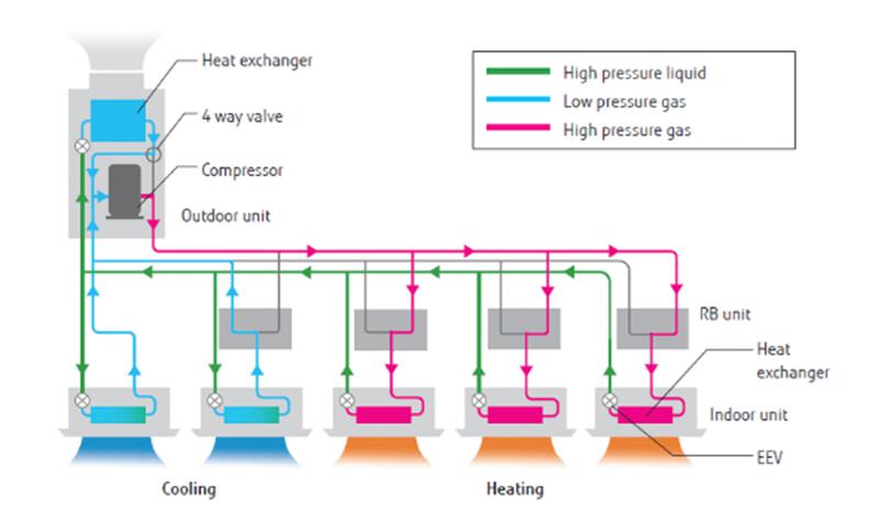
Figure 1 – Heat Recovery System Diagram. Source: firstgreen.co
Equipment Sizing

Figure 2 – Floor Mounted VRF Indoor Unit
While VRF systems can vary output to meet the load and are manufactured in a wide range of capacities, both indoor and outdoor units have minimum operating capacities. Therefore, in order to reduce cycling and over-conditioning of spaces, it is critical that the indoor and outdoor units are not over-sized.
Non-heat recovery VRF systems always have at least some minimum amount of refrigerant flowing through all the indoor units whenever at least one indoor unit is calling for heating or cooling. If an indoor unit is significantly oversized, the heat given off (or absorbed) by this refrigerant can overheat (or overcool) the space even when the fan coil is effectively “off.” Where loads are particularly small, such as in some Passive House buildings, low energy buildings, or micro-apartments, design engineers should be aware of the limited options for indoor units with low capacities. This effect can be exaggerated if the indoor unit requires its blower fan to run continuously, such as when the indoor unit is also providing ventilation air or if a return air temperature sensor is used to control the unit’s heating/cooling operation. (We will discuss more about ventilation and VRF in an upcoming blog post.)
Also note that indoor unit location (e.g., floor mounted, ceiling cassette, wall mounted) can have an impact on return air temperature.
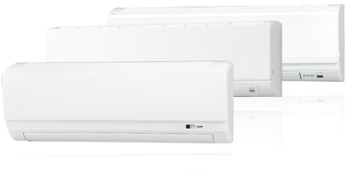
Figure 3 – Wall Mounted VRF Indoor Unit
Heating and Cooling Mode Changeover in Non-Heat Recovery VRF Systems
Because non-heat recovery systems must be entirely in either heating mode or in cooling mode, the system must have a method to select which mode it should be in. Methods to do so include the following:
- Manual changeover by a building operator via a central controller (e.g., in NYC, this changeover typically occurs at the start and end of “heating season” (October 1 through May 31);
- Choosing one “master” thermostat that controls the mode for the entire system;
- Based on outdoor air temperature;
- Some manufacturers’ or BMS vendors’ control schemes rely on more complicated algorithms that account for zone temperatures, distance from setpoints, and outdoor air temperature, among other factors.
 As building envelopes become increasingly well-insulated and air-tight, heat transfer to/from the exterior decreases but interior heat gains remain the same. Therefore, the building loads are increasingly “cooling-dominated,” effectively shortening the heating season (by up to several months). Design engineers and building operators must be aware of this rather significant change from “the norm” to properly size, zone, and operate systems for maximal occupant comfort.
If the building uses non-heat recovery VRF systems, the design team, ownership, and operations staff should discuss the desired method of mode changeover early in the design phase so that the necessary settings, sequences, and equipment are included in the project’s contract documents.
Manual Changeover
Manually changing the entire system into heating mode on October 1 will likely lead to overheating, due to the refrigerant continuously flowing through the indoor units as discussed in the previous section and the shifting “heating season.”
Outdoor Temperature or Standard Manufacturer Control Agreements
Theoretically, outdoor air temperature-based changeover can more accurately account for environmental conditions. However, fine tuning the changeover setpoint will be needed for each building to maximize comfort and minimize energy consumption.
Algorithmically-determined changeover programs typically use actual space temperatures and their deviations from the setpoints to determine whether the entire system should be in heating or cooling. This scheme works just fine when all the spaces served by that system need only heating, say. However, particularly during milder weather, the system might switch frequently between heating and cooling since it’s likely some residents will want cooling and some residents will want heating. As setpoints are satisfied, the balance of the changeover calculation then tilts toward the other mode, causing the entire system to switch over. This cycle will then repeat in the opposite direction. Furthermore, because most residents may not fully understand the details of how this VRF system operates, they will likely adjust their setpoint when they don’t receive expected heating or cooling, which further adds to the algorithm’s “confusion” about which mode the system needs to be in.
These constant mode changeovers result in increased energy consumption, uncomfortable residents, and unhappy supers. The compressor also stops and starts when switching between modes, which increases wear and tear on the compressor.
Conclusions
If there is one piece of information to take away from this blog post, it’s this:
For apartment space conditioning only use heat recovery VRF systems.
Even though it may seem there is no opportunity to use the “heat recovery” function of these systems in multifamily buildings, their utility extends well beyond that feature alone. Heat recovery VRF systems allow residents the flexibility to heat or cool their apartments to suit their needs, which reduces confusion and complaints directed towards building staff. It’s also pretty nice that heat recovery systems will reduce energy consumption 😊.
Terms
Variable Refrigerant Flow (VRF) –. VRF systems are heat pump systems that use variable speed compressors to vary refrigerant flow to satisfy part-load conditions. VRF systems provide heating and cooling, typically via multiple indoor units connected to a single outdoor unit. Some manufacturers refer to this technology as Variable Refrigerant Volume (VRV).
Indoor Unit – The equipment that is located in the conditioned spaces to provide heating and cooling to the space. These are also referred to as fan coil units (FCUs) or evaporators. VRF indoor units have a control valve that adjusts the flow of refrigerant through the unit to meet the heating or cooling demand of the space.
Outdoor Unit – The equipment that provides the shared heat rejection (in cooling mode) and heat absorption (in heating mode) capabilities for the entire system. They can reject/absorb heat either to the ambient air or to a to water loop. Outdoor units are sometimes also referred to as condensing units or condensers. They are not necessarily located outdoors, particularly in the case of water-cooled units.
Refrigerant – VRF systems utilize refrigerant, a medium that uses phase change between a liquid and a gas to transfer heat. Refrigerant piping runs between the outdoor units and the indoor units. Currently most VRF systems use R-410a, a non-toxic and non-flammable refrigerant that has a high global warming potential. (More to come on refrigerant management in a later blog post!)
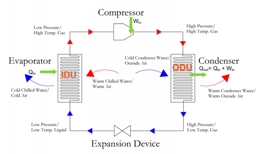
Figure 4 – Vapor Compression Cycle (Cooling Mode)

Written by Chris Lyle, Senior Building Systems Engineer
Keep up the great work, and I’m looking forward to reading more insightful articles from you in the future!
This cycle will then repeat in the opposite direction. Furthermore, because most residents may not fully understand the details of how this VRF system operates, they will likely adjust their setpoint when they don’t receive expected heating or cooling, which further adds to the algorithm’s “confusion” about which mode the system needs to be in.